Setting up and using physical server provisioning
In this topic, the following sections describe the full process necessary to set up and use physical server provisioning in BMC Cloud Lifecycle Management.
Before you begin
- Ensure that caching between BMC Cloud Lifecycle Management and BMC Server Automation has been established. It runs every 30 minutes by default. If necessary, you can force the caching by restarting the BMC_CSM service of the BMC Cloud Platform Manager (OSGi).
- To restart the BMC_CSM service under Microsoft Windows, use the stop\start commands of the Control Panel.
- To restart the BMC_CSM service under Linux, enter the following commands from the specified path on the command line:
/etc/init.d/bmccsm stop /etc/init.d/bmccsm start
- If you are not running OSGi as a service, then you can execute the following commands from the command line:
- To stop OSGi, enter Shutdown and then Exit.
- To run OSGi, use the following command:
-Xdebug -Xrunjdwp:transport=dt_socket,address=8654,suspend=n,server=y -jar org.eclipse.osgi_3.5.2.R35x_v20100126.jar -console -Xmx2048m -Xms512m -XX:MaxPermSize=256m
- The pod to be onboarded must already be configured in BMC Network Automation.
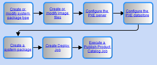
Overview of BMC Server Automation configuration tasks for physical server provisioning
The following sections provide an overview of the required tasks performed in BMC Server Automation to provision servers using BMC Cloud Lifecycle Management.
To create or modify the system package type
In the BMC Server Automation console, the System Package Types tab on the Provisioning Configurations window lists the available system package types. Use the following procedure to modify one of the available system package types to meet your provisioning needs. If necessary, create your own custom system package type. For example, you might create a custom system package type to deploy an operating system based on an earlier Microsoft service pack. To create a custom system package type, see the BMC Server Automation online techincal documentation.
To modify an existing system package type
- Select the System Package Types tab on the Provisioning Manager Configurations dialog box. A list of available OS packages is displayed.

- Double-click a system package type in the list to display the System Package Type dialog box.
- For Windows, select the processor architecture under the Windows Architecture option.
Specify file paths for the OS and agent installers in the OS Installer Configuration and RSCD Installer Configuration fields.
This file path is relative to the root path of the file server that you specify when you provision a device. Because the system does not validate the file path string, ensure that it matches the file path defined for the file server.
No absolute path name is entered for the installers. Remember to use the appropriate path separator in the path name: backslash for Windows and forward slash for UNIX or Linux.Tip
The file paths are usually located under the Datastore folder that you create for the PXE server. For more information, see Creating and stocking the data store in the BMC Server Automation online documentation.
- For Linux, specify the boot kernel files that correspond to the OS image pxeboot files from the tftproot pxelinux directory in the Boot kernal file name and Boot image file name fields.

- For Windows, indicate the initial partition size (megabytes) or accept the default value in the Initial Partition Size field.
- Click OK.
To create or modify the image files
The boot image (also referred to as preboot image) in BMC Server Automation is an object that contains a small operating system. This operating system, in turn, specifies how to start the bare metal machine or physical server and launch the installation of the actual operating system. WinPE is the boot image for Windows, and the Skip Linux pre-install method is the preferred boot image for Linux.
When executing a provisioning command, indicate which preboot image to use. BMC Cloud Lifecycle Management retrieves the preboot image in two ways:
- By selecting a hard-coded
BOOT_IMAGE_IDproperty definition on the device. This property definition can have a default value if all physical server devices use the same boot image. By attempting to match an appropriate boot image ID from the manufacturer attributes in BMC Cloud Lifecycle Management with the device. BMC Cloud Lifecycle Management uses the
PRODUCT_MANUFACTURERproperty on the BMC Server Automation provisioning image to determine the appropriate match.Note
The preboot image is supposed to have the PRODUCT_MANUFACTURER property automatically defined from the image type.
The procedure for creating a boot image file differs for Windows WinPE and Linux Gentoo.
To create a Windows WinPE boot image
Follow these summary guidelines to create a Windows WinPE boot image.
Make the necessary preparations on a system running the RSCD Agent:
- Install and configure the Windows Automated Installation Kit (WAIK), plus any additional utilities as required, as described in the BMC Server Automation online technical documentation
- Download the BMC Server Automation provisioning files from BMC Support, as described in the BMC Server Automation online technical documentation
- Carefully read the documentation about configuring WAIK in the BMC Server Automation online technical documentation.
Create the Windows WinPE boot image:
- On the BMC Server Automation Console, open the Configuration > Provisioning Image Creation dialog box, and follow the four-step wizard process.

- For the Boot Image Target Directory field, if applicable, specify a file path that resides under the updated /blfs/tftproot/ root directory path: for example, /blfs/tftproot/x64, where x64 indicates the processor architecture.
- Extract the WinPE boot files bootmgr.exe and pxeboot.0 so that the boot image can copy them to every TFTP server (application servers and repeaters).
- Above all, carefully read the documentation about Windows OS provisioning and WinPE boot files in BMC Server Automation online technical documentation.
To modify Windows image files
Note
Using multiple boot images for Windows is not supported, as BMC Cloud Lifecycle Management cannot set the appropriate boot image to the enrolled device.
- Select the Image Files tab from the Provisioning Manager Configurations dialog box to display a list of the available image types. Double-click the WinPE image type for the boot image you want to modify. The Edit Image File dialog box opens.

In the Image Path field, specify the relative path to the Windows boot image (the wim file), which is defined under the /blfs/tftproot/ directory. For example, if the boot image resides under /blfs/tftproot/X86PC/pxelinux/winpe2_x64, then enter winpe2_x64.
The wim file must have been created in the specified relative path: in this example, winpe2_x64.
- If the system is 64-bit, verify that 64-bit Image is selected.
- If the boot image is to be the default image based on WinPE version and processor architecture, select Set as default image.
To modify Linux image files
Starting in BMC Cloud Lifecycle Management 2.1 Service Pack 1 and later releases, you are no longer required to use the Gentoo boot image as long as the Skip Linux pre-install method is used.
To configure the PXE server
For both physical servers and bare-metal virtual machines, configure the PXE server. Before beginning the configuration steps, ensure that you have followed these guidelines:
- BMC recommends that you install the Preboot Execution Environment (PXE) server on a separate system rather than the same system where the BMC Server Automation Application Server is installed.
- If installing the PXE server on a Microsoft Windows system, configure and enable Internet Information Services (IIS). If installing on a Linux system, configure and enable Samba services.
- On the PXE server, set up a datastore directory to store server files, as in the following Windows example:

Configuring the PXE settings
You must configure a number items in the Provisioning Manager Configurations dialog box of the BMC Server Automation Console.
- From the BMC Server Automation Console, choose Configuration > Provisioning Configuration to display the Provisioning Manager Configurations dialog box.
- Select the PXE tab, and enter values according to the following guidelines.

- Override the default values only when you have specific reasons to do so. For example, accept the Use Multicast option and any supplied multicast address.
- In the Interface to bind field, enter the Ethernet card (for example, eth1) that the client uses to access the provisioning network.
- Enter a network domain in the Domain field.
- Use multicast as the internet protocol; do not select the Use Broadcast option.
Configuring the TFTP settings
- Select the TFTP tab from the Provisioning Manager Configurations dialog box.
- Override the default values only when you have specific reasons to do so.
- In the IP Address field, enter the IP address of the network interface card (NIC) that is bound to the provisioning network.
In the Base directory field, enter the full path of the tftproot directory, which is the base directory of the file system used to store operating system bootstrap programs to be downloaded.
Recommendation
If you are working in an environment with multiple PXE servers, BMC recommends that you create a new tftproot directory under the blfs folder: that is, /blfs/tftproot.
By default, the tftproot directory resides under the NSH scripts folder: /opt/bmc/bladelogic/pxe/NSH/tftproot. Because the blfs folder acts as the client's storage folder on application servers and repeaters, it can also function as the storage folder for OS boot images.
After you create the /blfs/tftproot directory, copy the contents of the existing /opt/bmc/bladelogic/pxe/NSH/tftproot directory to the newly created /blfs/tftproot directory.
Then edit the pxe.conf file, located under /opt/bmc/bladelogic/pxe/NSH/br, to
- indicate the revised tftproot directory path
- enable the local configuration file
- set the correct interface of the provisioning network
Some hardware models such as the Dell PowerEdge T310s/R710s and the HP DL380G6S, have newer firmware versions that increase the MFTFP timeout from a few seconds to up to ten minutes. Consequently, the provisioning process takes longer.
Guidelines for setting network shares in the PXE server environment
Follow these guidelines to establish network share drives in Linux and Windows environments.
| Environment | Task | Steps |
|---|---|---|
| Linux | Configuring the Samba server for Windows provisioning |
|
| Configuring HTTP for Linux provisioning |
| |
| Windows | Enabling Linux provisioning | Use Internet Information Server (IIS) to enable Linux provisioning. |
Configuring PXE server options
- Select BMC Software > BladeLogic Server Automation Suite > PXE-TFTP Server Configuration and Diagnostics Tool to display the PXE/TFTP Server Configuration dialog box.

- Select the Database tab of the PXE/TFTP Server Configuration dialog box, and enter the connection parameters of the database server.
- Select the PXE Options tab of the PXE/TFTP Server Configuration dialog box, and specify details about the network interface card (NIC) to which the virtual machine will be communicating with the PXE server. These details include the name of the interface, the multicast address, and the listening port.
Select the TFTP Options tab of the PXE/TFTP Server Configuration dialog box, and enter the details, including the TFTP root directory where the root image files and the IP address of the TFTP server are stored.
The PXE MAS Options and the PXE MAS Data Source tabs are optional.
After completing the PXE and TFTP options, select the Diagnostics tab of the PXE/TFTP Server Configuration dialog box, and click Run Diagnostics to check the status of your PXE and TFTP server processes.
Note
The diagnostic log will display an error message beginning with
Unable to open Datagram Socket on port ...if the PXE service is running on the specified port number. You can safely ignore the error message.
To configure the PXE datastore
Complete the steps in the following sections to configure the PXE datastore instance.
To create a PXE datastore instance
The Preboot Execution Environment (PXE) datastore is where boot image files, OS installers, and RSCD agent installers are stored. It is a subclass of the Property Dictionary. You must
- Create an instance of the PXE datastore
- Assign it a name in a required format that uses a pod name in the suffix
- Specify the full path to the datastore in the
Full Pathproperty
When a service offering request is made to provision a server, BMC Cloud Lifecycle Management searches the list of available datastores until it finds a match with the specified pod name.
- In the BMC Server Automation Console, select Configuration > Property Dictionary View to display the Property Dictionary.

- Expand Built-in Property Classes and locate the Datastore class.
- Expand the Datastore class and select PXE Datastore.
- Select the Instances tab in the adjoining pane.
Click Add New Property Set Instance to define the datastore instance and its properties.
Important
The name of the PXE datastore instance should follow this formatting convention:
CSM Datastore - name of pod (remember to add spaces on both sides of the hyphen). The pod you designate should be the pod you intend to onboard and provision with the physical server, bare metal virtual machine, or virtual guest server.- When defining properties for the datastore instance, ensure that the
FULL_PATHproperty points to the full path of the datastore directory you defined earlier on the PXE server, as shown in this Microsoft Windows example.
- Follow these guidelines:
- For the
LOCATIONproperty, enter the IP address or a DNS-resolvable host name of the PXE server where the datastore resides. - For the
VIRTUAL_DIRproperty, enter the name of the network share established for HTTP access to the OS images. - If the datastore network share is password protected, enter a user name and a password for the
USERNAMEandPASSWORDproperties.
- For the
- Click OK to save the data.
You can repeat these steps to create multiple PXE datastore instances.
Deploying a new VM to a local datastore
When provisioning a new VM to a local datastore (in contrast to a shared datastore), edit the providers.json file on the Platform Manager (OSGi) server.
- Log in to the computer where the Platform Manager product is installed.
- Open the providers.json file in a text editor.
By default, you can find the providers.json file in the BMCInstallSoftware\BMCCloudLifeCycleManagement\Platform_Manager\configuration folder. Change the
USE_LOCAL_DATASTOREattribute value from false (the default) to true.}, "attributeValue" : "true", "cloudClass" : "com.bmc.cloud.model.beans.AccessAttributeValue", "guid" : "7ef9f6e1-86ab-4f6b-8dc1-fceed3010c98", "name" : "USE_LOCAL_DATASTORE" } ],- Save the file.
Configuring the DHCP server
The BMC Server Automation provisioning process requires a DHCP server, which gives the computer being provisioned an IP address and (in a single-database environment) the location of the Application Server. The following topics describe the unique configuration needed so that a DHCP server can support BMC Server Automation's provisioning process:
Note
This task is required to set up a provisioning system. These steps assume that you understand how to install and configure a DHCP server.
BMC Server Automation requires you to:
- Have the TFTP server and the PXE Server reside on the same host computer
- Provide the IP address of the BMC Server Automation provisioning server
- Define a DHCP option field, which lets the computer being provisioned differentiate between a DHCP server and proxy DHCP servers
Note
BMC recommends that you do not configure the next-server and boot file image names on the DHCP server. In BMC Server Automation provisioning, the PXE server manages booting, not the DHCP server.
The following table describes how to define the DHCP option fields.
| Environment | Task | Steps |
|---|---|---|
| Windows | Add predefined options. A standard DHCP configuration should include the definition of a scope, which sets a start and end of the range of IP addresses being distributed. This range determines the number of servers that can simultaneously access the DHCP server.
|
|
Add option 60. If the DHCP server and the PXE server reside on the same host computer, you must add option 60 to let target computers differentiate between DHCP servers and proxy DHCP servers. If the DHCP server and the PXE Server reside on separate host computers, you do not have to perform this task. | ||
| Linux | Configure the dhcpd.conf file BMC Server Automation requires a Linux DHCP server to be running version 3.0p2 of the Internet Software Consortium (ISC) DHCP. The ISC provides a freely redistributable version of DHCP. Earlier versions of ISC DHCP are not compatible with the BMC Server Automation provisioning system. |
To create a system package
In order to perform an unattended installation of an operating system, create a system package (or modify an existing package) in BMC Server Automation for each server configuration you want to install.
To enable successful publishing of system packages for BMC Cloud Lifecycle Management, store the packages in the CSM_OS_Packages subfolder of the Depot folder in the navigation tree of the BMC Server Automation Console (Depot > CSM_OS_Packages): 
To create and define a system package
- Using BMC Server Automation, perform these initial steps necessary to create a system package.
The system package is created and opens in the content editor. - Define the system package by specifying all of its settings.
- See System package panels (OS specific) for detailed instructions about supported operating systems.
Review special considerations when defining system packages to determine if these instructions apply to your system package.
Note
When defining a system package, note the presence of the Select Property icon next to various input fields. Whenever you see this icon next to an input field, it indicates that you can insert a parameter that refers to a local property that supplies the value for the field.
- When entering or modifying parameters for the system packages, keep in mind these guidelines for BMC Cloud Lifecycle Management (Windows or Linux operating system):
- Under the Basic Config tab, enter ??NAME?? in the Computer name field. When the system package is selected at provisioning time, BMC Cloud Lifecycle Management supplies the hostname of the server to be provisioned or the IP address (if configured to do so).
- In the Local Properties tab, specify the name of the PXE datastore instance for the DATASTORE variable. Use the same format convention: CSM Datastore - <name of pod>.
- When you finish defining the system package, select File > Save.
Special considerations when defining system packages
Click any of the following tabs to review OS-specific considerations when defining system packages.
BMC Cloud Lifecycle Management cannot use Linux system packages with customized kickstart entries, which are defined under the Kickstart Entries tab. Instead, you can use the 'Additional entries for the kickstart file' section of the Kickstart Entries tab to append new entries for the system package.
When provisioning multiple network interface cards/addresses on Linux systems, add local properties to the system package using the following formats.
Note
Exclude the first address on the first network interface card. The first network interface card is assumed to be used for network booting.
Address |
Format |
|---|---|
Primary address on a network interface card, |
ETH<x>_MAC_ADDRESS |
For supplemental IP addresses on a network interface card, |
ETH<x>_<Y>_IPADDR |
The following example is for kickstart purposes and is added to the Additional entries for the kickstart file section. It assumes that you are provisioning for a Linux system package with more than one network interface and that the first network interface card has just one address and does not need to be covered. It also assumes that the second network interface card has two addresses on it.
echo "DEVICE=eth1" > /etc/sysconfig/network-scripts/ifcfg-eth1
echo "HWADDR=??ETH1_MAC_ADDRESS_CD??" >> /etc/sysconfig/network-scripts/ifcfg-eth1
echo "BOOTPROTO=??ETH1_BOOTPROTO??" >> /etc/sysconfig/network-scripts/ifcfg-eth1
echo "ONBOOT=yes" >> /etc/sysconfig/network-scripts/ifcfg-eth1
echo "IPADDR=??ETH1_IPADDR??" >> /etc/sysconfig/network-scripts/ifcfg-eth1
echo "NETMASK=??ETH1_NETMASK??" >> /etc/sysconfig/network-scripts/ifcfg-eth1
echo "GATEWAY=??ETH1_GATEWAY??" >> /etc/sysconfig/network-scripts/ifcfg-eth1

echo "DEVICE=eth1:0" > /etc/sysconfig/network-scripts/ifcfg-eth1:0
echo "HWADDR=??ETH1_1_MAC_ADDRESS??" >> /etc/sysconfig/network-scripts/ifcfg-eth1:0
echo "BOOTPROTO=??ETH1_BOOTPROTO??" >> /etc/sysconfig/network-scripts/ifcfg-eth1:0
echo "ONBOOT=yes" >> /etc/sysconfig/network-scripts/ifcfg-eth1:0
echo "IPADDR=??ETH1_1_IPADDR??" >> /etc/sysconfig/network-scripts/ifcfg-eth1:0
echo "NETMASK=??ETH1_1_NETMASK??" >> /etc/sysconfig/network-scripts/ifcfg-eth1:0
echo "GATEWAY=??ETH1_1_GATEWAY??" >> /etc/sysconfig/network-scripts/ifcfg-eth1:0
BMC Cloud Lifecycle Management cannot use Windows system packages with customized unattended entries, which are defined under the Unattended Entries tab. Instead, use the Additional Unattend Entries section of the Unattended Entries to replace existing or add new entries for the system package.
Follow these steps to add the XML entries to the system package:
- Under Additional Unattend Entries, click the Plus sign.
- In the top-left panel, expand the Specialize listing, and select the Microsoft-Windows-TCPIP node.
- Display the node by specifying a static IP address (which the system ignores).
In the Add/Replace XML Component section, paste the following XML code:
<component xmlns:wcm="http://schemas.microsoft.com/WMIConfig/2002/State" xmlns:xsi="http://www.w3.org/2001/XMLSchema-instance" language="neutral" name="Microsoft-Windows-TCPIP" processorArchitecture="amd64" publicKeyToken="31bf3856ad364e35" versionScope="nonSxS">WINDOWS_UNATTEND </component>
For SUSE Linux Enterprise System (SLES) 11, 64-bit, with a DHCP IP configuration: Create a Red Hat Linux system package by defining settings for the package as described here. In addition, make the following modifications:
- Basic Config tab — Set AutoYaST network device to
eth0. Post-Install Configuration tab — Add the following script:
echo "127.0.0.1 ??HOST_NAME?? localhost.localdomain" >> /etc/hosts echo " * rw,user=root" > /usr/lib/rsc/exports /etc/init.d/rscd stop /etc/init.d/rscd start echo "DEVICE=eth1" > /etc/sysconfig/network/ifcfg-eth1 echo "HWADDR=??ETH1_MAC_ADDRESS_CD??" >> /etc/sysconfig/network/ifcfg-eth1 echo "BOOTPROTO=??ETH1_BOOTPROTO??" >> /etc/sysconfig/network/ifcfg-eth1 echo "ONBOOT=yes" >> /etc/sysconfig/network/ifcfg-eth1 echo "STARTMODE=auto" >> /etc/sysconfig/network/ifcfg-eth1- Local Properties tab — Add the following local properties with a property type of String:
ETH1_BOOTPROTOETH1_MAC_ADDRESS_CD
For SLES 11, 64-bit, with a static IP configuration: Create a Red Hat Linux system package by defining settings for the package as described here. In addition, make the following modifications:
Post-Install Configuration tab — Add the following script:
echo "127.0.0.1 ??HOST_NAME?? localhost.localdomain" >> /etc/hosts echo " * rw,user=root" > /usr/lib/rsc/exports /etc/init.d/rscd stop /etc/init.d/rscd start echo "DEVICE=eth1" > /etc/sysconfig/network/ifcfg-eth1 echo "HWADDR=??ETH1_MAC_ADDRESS_CD??" >> /etc/sysconfig/network/ifcfg-eth1 echo "BOOTPROTO=??ETH1_BOOTPROTO??" >> /etc/sysconfig/network/ifcfg-eth1 echo "ONBOOT=yes" >> /etc/sysconfig/network/ifcfg-eth1 echo "STARTMODE=auto" >> /etc/sysconfig/network/ifcfg-eth1 echo "IPADDR=ETH1_IPADDR" >> /etc/sysconfig/network/ifcfg-eth1 echo "NETMASK=ETH1_NETMASK" >> /etc/sysconfig/network/ifcfg-eth1 echo "GATEWAY=ETH1_GATEWAY" >> /etc/sysconfig/network/ifcfg-eth1- Local Properties tab — Add the following local properties with a property type of String:
ETH1_BOOTPROTOETH1_GATEWAYETH1_IPADDRETH1_MAC_ADDRESS_CDETH1_NETMASK
For Oracle Enterprise Linux (OEL) 6.0, 64-bit, create a Red Hat Linux system package by defining settings as described here. In addition, make the following modifications:
Disk Partition tab — Specify the following partitions:
Mount Point
Type
Size (MB)
Fill Unused Space
N/A
swap
1024
false
/
ext4
5000
false
/boot
ext2
2048
false
- Basic Config tab — For Kickstart network device, enter
em1. Without this value, server provisioning fails. - Computer Settings tab — Select the following values:
- Keyboard — us
- Locale — English (USA english-support)
- OS Components tab — Select Base System.
- Network tab — Select Obtain an IP address automatically.
Kickstart Entries tab — Add the following additional entries for the kickstart file:
echo "DEVICE=eth1" > /etc/sysconfig/network-scripts/ifcfg-eth1 echo "HWADDR=??ETH1_MAC_ADDRESS_CD??" >> /etc/sysconfig/network-scripts/ifcfg-eth1 echo "BOOTPROTO=??ETH1_BOOTPROTO??" >> /etc/sysconfig/network-scripts/ifcfg-eth1 echo "ONBOOT=yes" >> /etc/sysconfig/network-scripts/ifcfg-eth1 echo "STARTMODE=auto" >> /etc/sysconfig/network-scripts/ifcfg-eth1 echo "IPADDR=ETH1_IPADDR" >> /etc/sysconfig/network-scripts/ifcfg-eth1 echo "NETMASK=ETH1_NETMASK" >> /etc/sysconfig/network-scripts/ifcfg-eth1 echo "GATEWAY=ETH1_GATEWAY" >> /etc/sysconfig/network-scripts/ifcfg-eth1- Post-Install Configuration tab — Enter the following values:
- IP address —
??APP_SERVER_IP?? - Port — 9131
- Post-Install Script —
echo "* rw,user=root" > /usr/lib/rsc/exports
- IP address —
- Local Properties tab — Add the following local properties with a property type of String:
ETH1_BOOTPROTOETH1_GATEWAYETH1_IPADDRETH1_MAC_ADDRESS_CDETH1_NETMASK
After you create the system package
After creating a system package, add a Network Shell (NSH) script called CSM_Delayed_Reboot to the Depot subfolder CSM_Scripts.
The script should look similar to the following example:
Type 1 (Execute the script separately against each target host.) |
Script: |
Parameter: hostname, default value TARGET.NAME |
To create the Deploy Job
This section provides high-level guidelines for creating a BLPackage Deploy Job. When you perform this procedure, you are creating software packages that you can use when defining an application in a service blueprint in BMC Cloud Lifecycle Management. Applications let you deploy software on VMs that you provision using the cloud.
Because the BLPackage Deploy Job supports blueprint parameterization, BMC recommends that you create a BLPackage Deploy Job instead of using an application component template.
For detailed information, see the following topics in the BMC Server Automation online technical documentation:
- Working with properties
- Working with components and component templates
- Deploying files and applications using packages and depot objects
- Creating and modifying Software and BLPackage Deploy Jobs
- If you plan to create an application component template, use BMC Server Automation to create Software Deploy Jobs to install applications on target virtual machines.
To create a BLPackage Deploy Job
BMC Server Automation BLPackages can be used to install applications on target virtual machines. A BLPackage is a collection of server assets, software packages, and an XML instruction set. A BLPackage can include installers, files, configuration objects, and so on. The BLPackage can also include parameterized property values among its server assets. The parameterized property values must match exactly the blueprint parameter values used by the service blueprint.
- Log on to BMC Server Automation.
- Click Depot.
- Open the BLPackage that requires a local property for editing.

- Click the Local Properties tab to add a local property to the BLPackage. In this example, HTTP_PORT is used.
- Click Add
 .
. Define the local properties that are used to parameterize the BLPackage. For example, you can add a local property called
HTTP_PORTthat you will use with a service blueprint.
Note
The name you assign to the local property must exactly match the name in the service blueprint.
In the example shown above,
HTTP_PORThas a default value of 80. When end-users request an offering from the Service Catalog, they can change the default HTTP port from 80 to the port number they require.Use the local properties as parameters you can pass in to the deployment of your application.
If the required object (file, configuration setting, registry key) does not already exist in the BLPackage, you must first import that server object into the BLPackage.
Parameterize the file by editing the BLPackage (for example, changing the object attributes).
Click the Package tab.
Select the new server object that you imported into the BLPackage.

Create a BLPackage Deploy Job that deploys the BLPackage that you parameterized.

Create the job in the CSM_Applications subfolder of the Jobs folder. Click the Package tab to view the local properties that you parameterized. Make sure the BMC Cloud Lifecycle Management administrator knows these parameters.
Set the following extended properties in the BLPackage Deploy Job:
PRODUCT_MANUFACTURERPRODUCT_NAMEPRODUCT_VERSIONThese values are written to the Product Catalog and can be found later when adding software packages to the service blueprint.
Execute the Publish Product Catalog Job to update the Product Catalog with the new object.

Note
A Publish Product Catalog Job is automatically created during installation in the CSM_Publish_Product_Catalog folder.
You can ignore warnings about Patch Catalog and Compliance templates.
All the Deploy Jobs where you set the PRODUCT_MANUFACTURER, PRODUCT_NAME, or PRODUCT_VERSION properties in the CSM_Application folder are published to BMC Cloud Lifecycle Management cloud database.
You now can use this parameterized BLPackage by adding it to an application in a service blueprint.
Note
A service blueprint parameter name must exactly match the name of a BLPackage's local property.
For more information about using parameters in a BLPackage, see Configuring service blueprint parameters, especially To configure parameters. For more information about adding applications to a service blueprint, see Creating, copying, or editing a service blueprint, especially To add and define applications in a service blueprint.
To execute the Publish Product Catalog Job
The Publish Product Catalog Job in BMC Server Automation retrieves a list of virtual guest packages and system packages from specially named BMC Server Automation folders, and publishes those to the Product Catalog. The Product Catalog is an application that is installed on the BMC Atrium CMDB and stores your hardware and software metadata. It is also known as the DML (Formerly DSL).
In BMC Server Automation, ensure that you have created the object to be published and stored the object in its appropriate folder, as described above.
To publish the product catalog
Note
Enabling the BMC Atrium Integration is a prerequisite for Publish Product Catalog Jobs. You specify the BMC Atrium CMDB instance from the BMC Server Automation Console through the Configuration > Atrium Integration > Configuration menu item.
- If you have already configured the CMDB in your BMC Server Automation Console, proceed to Step 4.
Choose Atrium Integration > Configuration from the Configuration menu and enter the following BMC Atrium CMDB details on the AR/CMDB Configuration tab:
AR/CMDB Configuration parametersParameter
Description
Host Name/IP Address
Host name or IP address of the computer where BMC Atrium CMDB is installed.
CMDB Port
Port used for communicating with BMC Atrium CMDB.
Note
If you are using a portmapper service for AR system, enter a value of 0.
CMDB User
User Name for connecting to BMC Atrium CMDB.
CMDB Password
Password for connecting to BMC Atrium CMDB.
- Click Test Connection to verify that the credentials that you entered are correct.
- Right-click the Jobs > CSM_Jobs folder, and select New > Publish Product Catalog Job.
- In the General panel, name the job and give it a description.
- In the Default Notifications panel, define default notifications that are generated when the job completes. Default notifications can take the form of e-mails or SNMP traps. For more information, see the Managing jobs topic in the BMC Server Automation online technical documentation.
- In the Schedules panel, schedule the job to execute immediately, at a specific time in the future, or on a recurring basis, and define notifications that are issued when the job runs. For more information, see the Managing jobs topic in the BMC Server Automation online technical documentation.
- In the Properties panel, there is a list of properties automatically assigned to each object. In this list, you can modify the value of any properties that are defined as editable. For more information, see the Setting values for system object properties topic in the BMC Server Automation online technical documentation.
- In the Permissions panel, grant roles access to any objects created in the system, such as jobs, servers, or depot objects. Using the Permissions panel, you can add individual permissions to an object. You can also set permissions by adding access control list (ACL) templates or ACL policies. For more information, see the Defining permissions for a system object topic in the BMC Server Automation online technical documentation.
- Click Finish to run the Publish Product Catalog Job.
- Review the job execution logs to verify that content created within the specially named folders in BMC Server Automation has been published into the BMC Cloud Lifecycle Management product catalog.
Viewing published objects in BMC Cloud Lifecycle Management
Objects published to the Service Catalog are available to the BMC Cloud Lifecycle Management Service Designer workspace, where they can be added to service blueprint components.
| Published objects | Applicable service blueprint components |
|---|---|
Software packages:
| Applications |
| OS packages | Servers |
| Virtual Guest Packages | Servers |
| Platform as a Service (PaaS) databases | PaaS Resources |
For more information about defining service blueprints, see Creating, copying, or editing a service blueprint. For more information about PaaS provisioning, see Setting up and using PaaS provisioning.
Overview of BMC Cloud Lifecycle Management configuration tasks for physical server provisioning
After completing the configuration steps to prepare the physical server for provisioning in BMC Server Automation, launch the BMC Cloud Lifecycle Management Administration console. In the console, establish the foundation for the provisioning service by onboarding and creating the related BMC Cloud Lifecycle Management resources.
The following sections provide an overview of this setup process. Each section provides a link to more details of each procedure.

To onboard the pod containing the PXE datastore instance
Onboard the pod containing the PXE datastore instance you created in BMC Server Automation. The format of the datastore instance name must be CSM Datastore - <name of pod>.
- From the BMC Cloud Lifecycle Management Administration Console, click the vertical Workspaces menu on the left side of the window and select Resources.
- Under Quick Links at left, click Pods under the General section.
- Click the Onboard Pod icon
 . The Onboard Pod dialog box is displayed.
- Click the Provider Name menu button to select the resource provider instance for the pod. The default network resource provider is listed as BBNA for BMC Network Automation.
- Select the pods that you want to onboard.
- Click Onboard to onboard the selected pods and close the dialog box.
For a more detailed procedure, see Onboarding and offboarding network pods.
To import the container blueprint
The next step is to import the container blueprint that the Publish Product Catalog Job has made available to BMC Cloud Lifecycle Management.
- From the BMC Cloud Lifecycle Management Administration Console, click the vertical Workspaces menu on the left side of the window and select Resources.
- Under Quick Links on the left, click Pods under the General section.
- Click the Import Network Container Blueprints icon
 .
.
The Import Network Container Blueprints dialog box is displayed. The dialog shows the Pod name, the version number (if the pod has been updated), and a description (if available).
- Select the network container blueprints that you want to import.
- Click Import to onboard the selected blueprints and close the dialog box.
For a more detailed procedure, see Importing network container blueprints.
To create the network container
To create a new network container, you launch a wizard that contains three dialog boxes. In the first dialog box, you specify the unique name of the container, its pod, network container blueprint, NAT range (if applicable), and any tags. In the second dialog, you specify networks, firewalls, and associated load balancers. In the third dialog, you enter any additional parameters.
- From the BMC Cloud Lifecycle Management Administration Console, click the vertical Workspaces menu on the left side of the window and select Resources.
- Under Quick Links on the left, click Network Containers under the Network section.
- Click the Create Network Container icon

The Create Network Container wizard is displayed.
Complete the following fields:
Field Description Name Required. Enter a unique name. The name can include only alphanumeric characters. It cannot include symbols or special characters such as a single quote (') or dollar sign ($). Description Provide a description that helps to distinguish this container. Tags Metadata that helps to define and classify the network container. Click the Add Tag icon to open the Tag Details dialog box from where you select or add a tag. See Creating tag groups and tags. Pod Select an appropriate pod from the list of available ones. Container Blueprint Select a network container blueprint from the list of available ones. The selection of the network container blueprint determines whether the container is dynamic and whether it supports Network Address Translation. NAT Address Pools This table shows the pools of registered IP addresses to which Network Address Translation can map an unregistered IP address. This section is enabled if the selected container blueprint supports Network Address Translation. Add NAT Address Pools Use the following fields to add a new NAT Address Pool: Address - Enter a single IP address to identify the starting point of the address range. Mask - 24\- or 32-bit mask that divides the IP address into subnets and identifies the available hosts in the network. Click Add to add the new NAT Address Pool. The Address in combination with the Mask defines the address range to be allocated for the network container. These fields are enabled if the selected container blueprint supports Network Address Translation. - Click Next to open the Dynamic Components dialog box. It displays the available networks and corresponding load balancers. For details, see Managing dynamic components for network containers.
The container will be provisioned on the network by BMC Network Automation using the specified network container blueprint.
For a more detailed procedure, see Creating network containers.
To onboard resources for physical servers
Before onboarding a physical server, ensure that the server is powered on. In addition, check whether values are assigned to properties in the Device class of the Property Dictionary in the BMC Server Automation console, as described in the following procedure.
- Open the Property Dictionary for the selected device in the BMC Server Automation Console.
- Expand the Built-in Property Classes folder, and select the Device class.
- Verify that values are assigned to the following properties.
Note
CPU_COUNT (Integer), CPU_FAMILY (String), and RAM_MB (Integer) properties, if the devices in the user interface are displaying the correct values for the corresponding properties.Property | Value |
|---|---|
| Number of CPUs for the device. If devices display in the interface showing the correct number of CPUs, do not set a value for this property. |
| CPU family for the device. If devices display in the interface showing the correct CPU family, do not set a value for this property.
(This listing will be updated with regular expression logic to cover likely discovered values.) |
| Correct amount of memory for the device. If devices display in the interface showing the correct CPU family, do not set a value for this property. |
| Required value. It is an entry for each network interface card (NIC) in the following format: mac-address, switch name, switch port. For example: |
To onboard the servers, complete the following steps:
For the Resource Type, select Physical Server for physical servers.
- From the BMC Cloud Lifecycle Management Administration console, click the vertical Workspaces menu on the left side of the window and select Resources
- Under Quick Links on the left, click Resources under the Compute section.
- Click the Onboard Resource icon
 .
.
The Onboard Resource dialog box is displayed.
- Select the Pod, Provider Name, and Resource Type for the resource you want to onboard. By selecting a Resource Type, you can onboard resources from a virtual cluster or physical server. When you onboard a virtual cluster, you are also onboarding the virtual hosts, virtual resource pools, and virtual disk repositories (also called datastores) associated with the virtual cluster. An alphabetical list of resources is displayed in the Available Resources table.
- Find the resources that you want to add.
- You can page through a long list by clicking the Page button
 .
. - You can search for resources by entering a search string in the Search box and clicking the search icon
 .
.
- You can page through a long list by clicking the Page button
Select one or more resources and click the Add button to move them to the Selected Resources table, or drag and drop resources from the Available Resources table to the Selected Resources table. When finished, click Onboard.
For a more detailed procedure, see Onboarding and offboarding compute resources.
To create compute resource pools
For the Resource Type, select Physical Server.
- From the BMC Cloud Lifecycle Management Administration Console, click the vertical Workspaces menu on the left side of the window and select Resources.
- Under Quick Links on the left, click Compute Pools under the Compute section. The list of current compute resource pools is displayed.
- Click the Create Compute Pool icon
 . The Create Compute Pool dialog box is displayed.
- Type a name for this pool.
- Type a useful description. Descriptions can help you distinguish pools from each other and can help you find a pool by using Search.
- If needed, create or select tags, as described in Creating tag groups and tags.
- From the Pod menu, select the network pod to which this pool will belong.
From the Resource Type menu, select the type of resources that this pool will contain:
Note
If you would like to place VMs on DRS-enabled clusters, make sure to set up Compute Pools of VirtualClusters. If you would like to place VMs on non-DRS clusters, make sure to setup your Compute Pools of VirtualHosts or VirtualResourcePools.
Virtual Cluster—You must also pick the Vendor and HW Architecture of the cluster.
Physical Server—You must also pick the HW Architecture of the server.
Virtual Resource Pool—You must also pick the Vendor and HW Architecture of the virtual resource pool.
Virtual Host—You must also pick the Vendor and HW Architecture of the virtual host.
Virtual Disk Repository—You must also pick the Vendor of the virtual disk repository.
From the Provider Type menu, select the provider for this pool.
From the Vendor menu, select the vendor for the compute resources in this pool.
From the Hardware Architecture menu, select the architecture type for the compute resources in this pool.
Click Next.
The Create Compute Pool Resources dialog box is displayed.
Availability column—This column is displayed for the Virtual Resource, Virtual Host, and Virtual Disk Repository resource types. A value of Available indicates that the virtual resource can be used as an active resource in the compute pool. Items displayed as Unavailable have been marked for deletion and should not be included as a compute resource for the pool.
Type column—This column is displayed for the Virtual Disk Repository resource type. If you are adding a compute pool with a Virtual Disk Repository resource type, you will also see a Type column on this dialog box. If the resource is a VMware datastore cluster, you will see the following format in the Type column: Cluster:<fileType>. For example, a VMware Virtual Machine File System (VMFS) data store cluster would be displayed in the Type column as Cluster: VMFS.
Click Save to create an empty pool or continue with the following steps to add resources to the pool.
Find the resources that you want to add.
You can page through a long list by clicking the Page button
 .
. You can search for resources by entering a search string in the Search box and clicking the search icon
 .
.
Select one or more resources and click the Add button to move them to the Selected Resources table. You can also drag and drop resources from the Available Resources table to the Selected Resources table.
Click Save.
For a more detailed procedure, see Creating compute resource pools.
To import tenants
- From the Administration Console, click the vertical Workspaces menu and select Tenants.
- In the Tenant Management pane, click Create or import tenant
 .
. - In the Add Tenant dialog box, enter the required details.
Fields marked with an asterisk (*) are mandatory.- Select the Import Existing Tenant button.
From the Company Name list, select the tenant that you want to import.
The Company Name list comprises the tenants created in BMC Remedy IT Service Management Foundation, which are not yet imported. After you select the tenant, the details are displayed. You cannot edit the tenant details from BMC Cloud Lifecycle Management.Note
You cannot import a tenant if the location for the tenant is not specified in BMC Remedy ITSM Foundation.
Click the Contract End Date calendar icon and select the date when the tenant's users will no longer to be able to request cloud services in the BMC My Cloud Services Console.
Note
The Contract Start Date is set to the date that you onboard the tenant and you cannot change it. The Contract Start Date defaults to the start of the day, at 12:00 A.M. To increase the the length of the contract to the end of the day, add an additional day.
- From the list of Available Entitlement Packages, select the packages you want to apply to this tenant.
- Click Add > to move them to the Selected Entitlement Packages area.
You can use the search field to search for the preferred entitlement package. For details about the entitlement packages, see Creating entitlement packages. - Click the Quotas tab to define the quota for the tenant.
By default, the Unlimited check box is selected for a tenant. For details about quota, see Setting and managing quota. - If you want to specify a limited quota for the tenant, perform the following steps in the Allocation area:
- Clear the Unlimited check box for the Server, CPU Count, Memory (GB), and the Local Storage (GB) fields.
- In the Tenant Quota text box for the Server field, enter the number of servers that you want to assign to the tenant.
- In the Tenant Quota text box for the CPU Count field, enter the number of CPUs that you want to assign to the tenant.
- In the Tenant Quota text box for the Memory (GB) field, enter the memory in GB that you want to assign to the tenant.
- In the Tenant Quota text box for the Local Storage (GB) field, enter the local hard disk in GB that you want to assign to the tenant.
- Click Add.
The tenant is imported successfully.
To verify whether the tenant is onboarded successfully, click the Activities tab. The Update Tenant Quota activity and its status are displayed.
For a more detailed procedure, see Creating and importing tenants.
To create entitlement packages
Entitlement packages are groups of requestable offerings to make available to one or more tenant companies.
- From the BMC Cloud Lifecycle Management Administration Console, click the vertical Workspaces menu on the left side of the window and select Service Catalog.
- Click the Entitlement Packages tab.
The Packages workarea is displayed. - Click the Create Entitlement Package icon
 .
.
The Package Details dialog box is displayed.
- Enter a name for the package.
- Enter a description.
- In Company, select the tenant company for the package or select Global to make the package available to all companies.
- You can enter or select a package group.
Package Group marks a package as being part of a group. The Package Group value is not used anywhere else. - In the Available Requestable Offerings (SRDs) table, select the offerings that you want to make available to the selected company.
- Click Add to move the offering to the Selected Requestable Offerings (SRDs) table.
You can also drag and drop entitlement packages from one table to the other. - Click Save.
- Click Close.
You can now associate the new entitlement package with a particular tenant company, as described in Selecting tenant entitlement packages.
For a more detailed procedure, see Creating entitlement packages.
To map compute resource pools to network containers
- From the BMC Cloud Lifecycle Management Administration Console, click the vertical Workspaces menu at left and select Resources.
Under Quick Links at left, click Network Containers under the Network section.
- Select the network container to which you want to map one or more resource pools.
- Click Manage Pool Mappings
 .
.
The Map Pools dialog box opens.
- Find the resource pools that you want to add to the network container:
- You can page through the list by clicking the Page button
 .
. - You can search for resource pools by entering a search string in the Search box and clicking Search
 .
.
- You can page through the list by clicking the Page button
- Select one or more resource pools in the Available Pools table and click Add to move them to the Mapped Pools table.
You can also drag and drop resource pools from the Available Pools table to the Mapped Pools table. - Click Save.
The selected pools are mapped to the network container.
For a more detailed procedure, see Mapping resource pools to network containers.
To map tenants to network containers
- From the the BMC Cloud Lifecycle Management – Administration Console, click the vertical Workspaces menu and select Resources.
- Under Quick Links > Network section, click Network Containers.
- Select the network container to which you want to map one or more tenants.
- Click Manage Tenant Mappings
 .
.
The Map Tenants dialog box is displayed for the selected network container. In the Name field, the name of the tenant is displayed. In the Available Tenants table the list of onboarded tenants is displayed.
Select one or more tenants from the tenants table and click Add >.
The selected tenant or tenants are moved to the Mapped Tenants table. You can search for a tenant by using the Search field.Note
The Search field is case-sensitive.
- Click Save.
The selected tenant or tenants are mapped to the network container.
For a more detailed procedure, see Mapping tenants to network containers.
To define the service blueprint
Prior to defining the service blueprint, review the prerequisites.
Do one of the following:
If you want to... Complete these steps Create a new blueprint - In the Service Designer workspace, click Create New, and then select the type of blueprint you want to create.
A new service blueprint is opened in the Blueprint Editor. By default, you begin working in Definition 1.
If you are creating an Application, Server, or PaaS Blueprint, your blueprint will contain only one application, server, or PaaS database object. Click Save.
- Enter a unique name for your blueprint to describe the application or server type (for example, LAMP Gold or MediaWiki).
Provide a Description.
Click OK.
Copy an existing blueprint - In the Service Designer workspace, click a service blueprint in the Blueprint Library.
The service blueprint appears in view-only mode. - Select Version > Clone.
Enter a unique name for your blueprint to describe the application or server type (for example, LAMP Gold or MediaWiki).
Click Create Copy.
The new service blueprint is opened as a working copy and is available to edit.
- In the Service Designer workspace, click Create New, and then select the type of blueprint you want to create.
- As needed, add and define the components in your blueprint.
To add components and define compute resources
Whether creating, copying, or editing a service blueprint, you can add several different types of objects, and define network connections between those objects in many ways. The procedures referred to in the table below offer a suggested path through the initial creation process, though you can add some or all of these objects in almost any order.
| To add this component or resource | See |
|---|---|
Servers | |
| PaaS resources | To add and define PaaS resources in a service blueprint |
| Applications | To add and define applications in a service blueprint |
| Networks and connections | To add and define networks and connections in a service blueprint |
| Load balancer pools | To add and define load balancer pools in a service blueprint |
| IP endpoints and VLANs | To add and define IP endpoints and VLANs in a service blueprint |
| Service blueprint definitions | To define definitions for a service blueprint |
| Service blueprint properties | To define the properties of a service blueprint |
To create the service offering
Use the Service Catalog to create services, which are composed of one or more service offerings and requestable offerings. You create services and offerings to provide cloud services that your user can request. For overview information about services, see Services overview.
Except storage services, a service blueprint is required for all services, as described in Building service blueprints. You can start creating the service without a service blueprint, but you must select a service blueprint in order for the service to be functional.
- Create a new service, as described in Creating new services for the Service Catalog.
- Create a service offering, as described in Creating a service offering.
- Create a requestable offering, as described in Creating a requestable offering.
- Create options for services, as described in Service Catalog options and option choices.
To make the provisioning request
- Access Workspaces > Service Instances to display the Service Instances workspace, and click the New Service Request icon to display the New Service Request dialog box.
- In the New Service Request dialog box, click the server provisioning service you want to request to display the Submit Request dialog box.
- Enter the data in the required fields to complete the request for an instance of the service request. You can click Next to review the details.
- Click Submit. The request is added to the Pending Activity list in the Service Instances window.
The request status is displayed in the Pending Activity list of the Service Instances window. You can double-click on the service request to see its detailed information.
For more detailed procedures, see Requesting cloud services.
Related topics
Setting up and using PaaS provisioning
Setting up and using bare-metal VM provisioning
Setting up and using VM provisioning (from VMware VM template)
Comments
Log in or register to comment.