Provisioning VMs on VMware vCenter using Quick Start
Quick Start asks you to provide a limited number of configuration settings for BMC Cloud Lifecycle Management so it can fulfill end user requests for automated provisioning of virtual machines (VMs). When you provide configuration information in Quick Start, you identify existing resources. By deriving information from those resources, Quick Start is able to create the generalized definitions that BMC Cloud Lifecycle Management needs to perform provisioning.
This topic describes the end-to-end vCenter approach in Quick Start. It includes the following sections:
Video demonstration
You can view a video that demonstrates how to use the vCenter approach to configure BMC Cloud Lifecycle Management so it can fulfill end user requests for automated provisioning of VMs.
Use player to increase quality or switch to full screen | YouTube:
https://www.youtube.com/watch?v=ibBL_UxHb9o

Video contents
| Time stamp | Topic |
|---|---|
| Prerequisites | 00:30 |
| vCenter connector | 01:48 |
| vCenter environment | 05:00 |
| vCenter services | 06:55 |
| Tenants and users | 09:55 |
| Provisioning | 11:30 |
Before you begin
- Log onto BMC Cloud Lifecycle Management using a cloud administrator account. The cloud administrator must be associated with a provider company. (Click here for details about creating a provider company and a cloud administrator account.) When completing the BMC Remedy AR Systems form for the cloud administrator account, be sure to check Unrestricted Access.
If you do not use the Cloud Admin template to create the cloud administrator account (the standard approach), create a provider company for the new cloud administrator account and then ensure the account has the following permissions:- Cloud Admin
- Contact Organization Admin
- Install a Windows RSCD agent on the vCenter server.
- Ensure that BMC Network Automation is configured so that virtual data centers are enabled.
- Ensure that conditions in any policies already defined in BMC Cloud Lifecycle Management are set to "Match Any." Quick Start creates its own policies that may conflict with existing policies. For more information, see Adding and editing policies.
Use VMware vCenter Server to create templates from existing virtual machines. For more information on that process, see VMware vCenter online documentation.
- Be aware that you can only use Quick Start to create new configurations for BMC Cloud Lifecycle Management. You cannot modify existing configurations.
- Optionally, review the complete list of required settings before using Quick Start.
High-level steps

To access Quick Start, click the vertical Workspaces menu on the left side of the BMC Cloud Lifecycle Management Administration Console. Then click Quick Start. The Quick Start welcome page opens. It provides links to wizards that step you through the process of configuring Quick Start.
On the welcome page, two links apply to the vCenter-based provisioning:
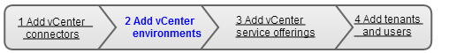
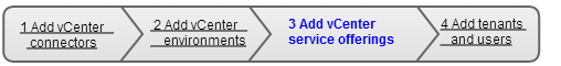
- New VMware Setup — Steps you through three procedures needed to set up provisioning using a vCenter server:
- Adding a vCenter connector — Provide information that represents a connection to a vCenter server.
- Adding vCenter environments — Use the vCenter connector to identify a set of virtualized hardware and associated network configurations.
- Adding vCenter service offerings — Define a service offering based on a Virtual Guest Package (VGP) of an existing VMware vCenter template.
- New Tenant and User — Identify tenants, the offerings to which those tenants are entitled, and the users associated with those tenants.
After you complete the Quick Start process, users can request VMware VMs using the BMC Cloud Lifecycle Management - My Cloud Services Console.
Adding a vCenter connector

In Quick Start, a connector defines a VMware vCenter and a set of shared network resources for the vCenter.
If a failure occurs while adding a vCenter connector, Quick Start automatically rolls back all content.
To add a vCenter connector
On the Quick Start home page, click New VMware Setup.
This page provides information that lets Quick Start use BMC Server Automation to connect to a vCenter server.

This page also provides a vertical navigation bar at left, which illustrates where you are in the Quick Start process.
Complete the Setup Connector page.
Option
Description
vCenter Web Service Protocol
Select http or https. BMC recommends https.
vCenter Hostname
Fully qualified name or IP address of the vCenter server.
vCenter Web Service Port
Port number for the web service interface to the VMware vCenter. The port number can be any value between 1 and 9999. 443 is typical.
User Name
User name of an administrator for the vCenter server who can access BMC Server Automation. Providing user credentials allows Quick Start to instruct BMC Server Automation to perform certain actions. The user you identify must have a set of minimum privileges on the vCenter server.
Password
Password for the administrator of the vCenter server who can access BMC Server Automation.
Confirm Password Re-type the password. Click Next to display the Network Credentials page.
The Network Credentials page asks for information needed to set up a network that a provisioned VM will use. A network created while setting up the vCenter connector is called a network pod. BMC Cloud Lifecycle Management can create groupings of networks, called network containers, to which specific tenants are entitled. In Quick Start, you create network containers later in the process when you define vCenter environments.
BMC Cloud Lifecycle Management has the ability to define shared networks. For instance, many companies create one network for development services and another for production services. However, both these services might also share a management network that is used to communicate with monitoring tools or network storage.
You are not required to specify a network here at the pod level. However, if you do not specify a network pod, you must define at least one network later when you add a vCenter environment.

- Complete the Network Credentials page.
Option
Description
Data Center Location
Select the location of the datacenter. For new installations, you must enter the data center location rather than selecting an option from a list.
Network Switch Type Select the types of switches included in the network you are defining. The page displays different options depending on the type of switch you select.
- vSwitch/dvSwitch—Virtual or distributed virtual switch.
- Nexus 1000V—Cisco Nexus 1000V switch
- Both—Network includes both a virtual or distributed virtual switch and a Cisco Nexus 1000V switch.
User Name
Name of the vCenter server administrator who can access BMC Network Automation, which creates network pods. This option only appears if you have set Network Switch Type to vSwitch/dvSwitch or Both.
Password
Password for the BMC Network Automation administrative user.
Confirm Password Re-type the password for the BMC Network Automation administrative user. Nexus 1000V User Name Name of a user who can view and modify Cisco Nexus 1000V switches. This option only appears if you have set Network Switch Type to Nexus 1000V or Both. Nexus 1000V Password Password for the Cisco Nexus 1000V user. Confirm Password Re-type the password for the Cisco Nexus 1000V user. - Click Next to display the Network Pod page.
The Network Pod page lets you define networks that are shared across all of the environments in a vCenter connector. For instance, many cloud environments share a common management or storage network. Other networks are specific to one environment, such as production or development networks or networks made available to particular tenants. You define environment-specific networks when you add vCenter environments.You are not required to specify a network at the pod level. If you do not specify a network on this page, you must define at least one network when you add a vCenter environment.

- Complete the Network Pod page.
Provide information about the network you are identifying that will be used to create the network pod.
You are not required to specify a network at the pod level. If you do not specify a network here, you must define at least one network when you add vCenter environments.Option
Description
Port Group
The port group that aggregates the ports available to the network you are provisioning.
Management
A flag indicating whether the network is used for management purposes.
Customer A flag indicating the network is used for customer purposes. Network Alias
An identifying name for the network. Select from the list of typical aliases or enter your own name.
Gateway
Address of the IP router that is used to forward traffic to destinations outside of the local network. For example, 10.0.0.1.
Network
The IP address for this network. Available addresses within the network address can be further specified using the subnet value. For example, 10.0.0.0.
Subnet Mask
A range of IP addresses that are available to the network address. For example, 255.255.255.0.
At any time, you can discard the network information by clicking Remove. The network definition is removed. You can start defining a new network by clicking Add Network
 .
.To exclude one or more IP addresses from a network, perform the following steps:
- Click Add An Excluded IP or Range.
Additional options appear. Use them to specify IP addresses that should be excluded from the network you are currently defining. Typically, you exclude a network address when it is already being used for other purposes. - To specify one IP address to exclude, enter a value for Start IP Address. To specify a range of IP addresses, enter a value for Start IP Address and End IP Address.

- Repeat the previous steps to specify another address or range of addresses to exclude.
To remove an excluded address or range of addresses, click Remove.
- Click Add An Excluded IP or Range.
(Optional, starting with BMC Cloud Lifecycle Management 4.1 patch 1 and later) To configure DNS registration details for the pod, perform the following steps:
Click Add DNS Registration details.
Additional options appear. Use the following table to specify the DNS registration details for the pod.Option Description Primary DNS Server A valid hostname or IP address of the primary DNS server. Reverse DNS Server A valid hostname or IP address of the reverse DNS server that allows reverse lookup of the IP address. Secondary DNS Server A valid hostname or IP address of the secondary DNS server. Primary Domain Fix The primary domain fix for the NIC. DNS Domains The DNS domains for the NIC. You can specify multiple domains in a comma-separated list. Reverse DNS Zone The reverse DNS zone where the PTR-record type stores reverse DNS entries. To remove the DNS registration details, click Remove.
- When you complete a definition for a network, click Keep (at top right).
Quick Start shows a summary of the network definition.
To remove a definition for a network, click Remove. - To define an additional network, click Add Network and repeat the previous steps.
When you finish defining networks, click Next.
The vCenter connector is complete. Quick Start opens the New Environment page, the first step in defining a vCenter environment.
Quick Start interactions with BMC Cloud Lifecycle Management
Back to High-level steps
Back to top
Adding vCenter environments
A vCenter environment defines the compute, storage, and network resources available for a virtual machine. Essentially, a vCenter environment is one or more VLANs that provide network isolation for tenants in the cloud.
If a failure occurs while adding a vCenter environment, Quick Start automatically rolls back all content.
To add a vCenter environment
- Complete the New Environment page.
This page lets you provide information that defines a new vCenter environment. Quick Start uses this information to create a network container in BMC Cloud Lifecycle Management.
Option
Description
Environment Name
Name to assign to the vCenter environment. Quick Start uses the environment name when it creates a network container and a tag in BMC Cloud Lifecycle Management.
Description
Description of the vCenter environment.
vCenter Server
The vCenter server that is specified for the vCenter connector.
- Click Next to display the Compute Pools page.
The Compute Pools page lets you select the clusters and resource pools managed by the VMware Distribute Resource Scheduler (DRS) to include in your environment's compute pool. You can also select hosts not managed by DRS.
- Click Next to display the Data Storage page.
The Data Storage page lets you select vCenter datastores to include in your environment's compute pool.
- Click Next to display the Networks page.
The Networks page lets you define networks within an environment (that is, within a network container in BMC Cloud Lifecycle Management). You accomplish this by identifying networks that already exist on a port group. Quick Start can use the information about existing networks to define networks where virtual machines can be provisioned.
The Networks page also shows networks that were identified while defining a vCenter connector. These "pod-level networks" have only one editable option, Network Alias. You can override the network alias in the context of this environment.

Provide information about a new network.

Option
Description
Port Group
The port group that aggregates the ports available to the network you are provisioning.
Management A flag indicating whether the network is used for management purposes. If you do not specify a network at the pod level and you only specify one network at the environment level, you must indicate that the network be used for both management and customer purposes.
Customer A flag indicating the network is used for customer purposes. If you do not specify a network at the pod level and you only specify one network at the environment level, you must indicate that the network be used for both management and customer purposes. Network Alias An identifying name for a network created in BMC Cloud Lifecycle Management. Choose from the list of typical aliases or enter your own name. The alias is also used for generating a tag.
For pod-level networks, identified while connecting to a vCenter, you can modify the Network Alias.
Gateway
Address of the IP router that is used to forward traffic to destinations outside of the local network. For example, 10.0.0.1.
Network
IP address for this network. Available addresses within the network address can be further specified using the subnet value. For example, 10.0.0.0.
Subnet
A range of IP addresses that are available to the network address. For example, 255.255.255.0.
At any time, you can discard the network information by clicking Discard. The network definition is removed. You can start defining a new network by clicking Add Network
 .
.To exclude one or more IP addresses from the network you are defining, perform the following steps:
- Click Add An Excluded IP or Range.
Additional options appear. Use them to specify IP addresses that should be excluded from the network you are defining. Typically, you exclude a network address when it is already being used for other purposes. - To specify one IP address to exclude, enter a value for Start IP Address. To specify a range of IP addresses, enter a value for Start IP Address and End IP Address.

- Repeat the previous steps to specify another address or range of addresses to exclude.
To remove an excluded address or range of addresses, click Remove.
- Click Add An Excluded IP or Range.
- When you complete a definition for a network, click Keep (at top right).
Quick Start shows a summary of the network definition.
To remove a definition for a network, click Remove. All data for the network is deleted. - To begin defining another network, click Add Network .
When you finish defining networks, click Next.
The vCenter environment is complete. Quick Start opens the Template page, the first step in defining a vCenter service offering.
Quick Start interactions with BMC Cloud Lifecycle Management
Back to High-level steps
Back to top
Adding vCenter service offerings
You must define an offering that end users can choose in a service catalog when they are provisioning virtual machines (VMs).
When you define services, you identify an existing VM template that Quick Start uses as the basis of a Virtual Guest Package (VGP). You also specify network information needed to provision the VM. When provisioning actually occurs, the VGP provides an instruction set and any files needed for implementing the configuration of the new virtual machine.
To add vCenter services from templates
- Complete the Template page.
The Template page lets you name the service offering you are creating and select the VM template that is deployed when a user requests this service.

Option
Description
Service Name
Name of the service you want to offer in the service catalog.
Service Description
Descriptive text for the service.
vCenter Server
The vCenter server identified when you establish a vCenter connector.
VM Template
A VM template chosen from the list of VM templates available to the vCenter server.
Note
Starting with BMC Cloud Lifecycle Management 4.1 patch 2 and later, if the VMs in the VM templates are configured to connect to a vApp network, BMC Cloud Lifecycle Management creates the blueprints with VM NICs tagged with the corresponding vApp network. When you provision a new SOI with this blueprint, the vApp is created with VMs connected to the vApp network.
OS Key
The key to the operating system license you are using, including all hyphens in the key. This license is only required when provisioning Windows VMs.
Admin Password
A phrase that will be configured as the administrator's password on the virtual machine.
Confirm Password Re-type the password for the administrator. - Click Next to display the Service Offering page.
The Service Offering page lets you specify the processing capabilities and network interface cards (NICs) that will be provisioned to virtual machines.
- Enter the characteristics of the VM to be provisioned.
Option
Description
CPU Count
Select the number of CPUs for the VM being provisioned.
Memory (MB)
Select the amount of memory, in megabytes, that is available to the VM being provisioned.
Price
(Optional) Enter the amount a user is charged for use of a virtual machine for a specified period of time. For example, 20 dollars per month.
Currency
Select the type of currency, such as U.S. dollars (USD).
Period
Select the length of time for which a user is charged for use of a virtual machine.
Include CPU & Memory Options Indicates the service offering will include out-of-the-box options that allow the end user to specify the CPU count and memory. - Click Add New
 to add a Network Interface Card (NIC).
The Service Offering page displays a row of options you can use for defining a NIC, as described below.

Option
Description
Network Alias
Identifying name for the network to which this NIC connects. Choices are derived from network aliases specified while connecting to a vCenter (that is, defining a connector) and defining networks for the environment.
Address Pool
Select one of the following options. You must designate at least one NIC for management purposes.
- Static — An IP address for the NIC is based on the network, subnet, and excluded address information provided while connecting to a vCenter and defining networks for the environment.
- DHCP — An IP address for the NIC is automatically obtained from a DHCP server each time the virtual machine boots up.
Management Network
A flag indicating whether the network is used for management purposes. At least one management network is required.
At right on each row, icons let you delete a NIC, move it up, or move it down.
You may want to reorder NICs because the default network path for the server is routed through the first NIC in the list. For example, if only one NIC allows Internet traffic, you probably want to position that NIC as first in the list.
- When you finish defining services, click Next.
VMware setup is complete. Quick Start displays a summary page showing all the configuration settings you have chosen. - After reviewing the summary page, click Finished.
The Quick Start home page opens. You can now set up tenants and users.
Quick Start interactions with BMC Cloud Lifecycle Management
Back to High-level steps
Back to top
Adding tenants and users

You must define the entitlements that are available to tenants. An entitlement is a set of service offerings that a tenant can request. A tenant in BMC Cloud Lifecycle Management can be a company, organization, or any other group of users. By setting up tenants, you can segregate companies or organizations in the cloud. You can also control what entitlement packages are available for each tenant.
You must also create users that are associated with a tenant.
If a failure occurs while adding tenants, users, and entitlements, Quick Start automatically rolls back all content.
To add tenants, entitlements, and users
On the Quick Start welcome page, click New Tenant and User. The Add Tenant page opens.
This page provides the information needed to define a tenant and the entitlements available to the tenant.

Option
Description
Name
Name of the tenant.
Location
Location of the tenant.
This location does not have to be the same as the location of a vCenter server you specify when creating a vCenter connector.
Environment Entitlement
Associates the tenant with an environment.
Offering Entitlement
Identifies the service offerings to which the tenant is entitled. For each offering you select, you must ensure that the associated environment (specified with the Environment Entitlement option) is also selected.
Note
If you map multiple environments with different network aliases to a single tenant, subsequent provisioning attempts in BMC Cloud Lifecycle Management may fail with policy validation errors.
If you map multiple environments created from multiple network pods to a single tenant, provisioning may fail because the environment chosen during provisioning may be incompatible with the VM Template or AMI used for service creation.
- Complete the page and click Next to display the Add User page.
This page provides the information needed to define a new user for a tenant.
Option
Description
First Name
User's first name.
Last Name
User's last name.
Login Name
User's logon ID
Password
User's password.
Confirm Password Retype the user's password. Role
One of the following user roles:
- Cloud Admin—Manage the full life cycle of the cloud environment, including its initial planning, deployment, and configuration, and its continued administration, operation, and maintenance.
- Org Admin—Manage a subset of the cloud to perform tasks such as monitoring usage, administering virtual firewalls, and maintaining virtual load balancers.
- End User—Request services, such as the deployment of virtual machines (VMs), through the BMC My Cloud Services Console.
Tenant Company
Tenant that is associated with this user.
- Complete the Add User page and click Next to view a summary of the choices you have made for tenants and users.
- Click Finished.
Quick Start interactions with BMC Cloud Lifecycle Management
Back to High-level steps
Back to top
Comments
Log in or register to comment.